ECM
Equivalent Circuit Model
1. Model Introduction
The equivalent circuit model uses traditional resistors, capacitors, voltage source and other circuit components to form a circuit network to describe the external characteristics of the power battery. The model uses a voltage source to represent the thermodynamic equilibrium potential of the power battery, and uses an RC network to describe the dynamic characteristics of the power battery. The equivalent circuit model has good applicability to various working states of the power battery, and the state equation of the model can be deduced, which is convenient for analysis and application. Equivalent circuit models have been widely used in new energy vehicle modeling and simulation research and model-based BMS algorithm development. The figure below shows a typical equivalent circuit model of a power battery composed of n-RC network structures, referred to as n-RC model.
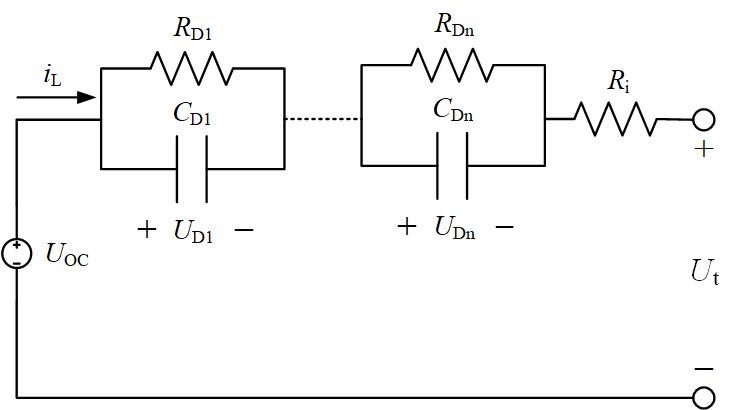
Fig. 1. N-RC equivalent circuit model
The model is composed of three parts: (1) Voltage source: use UOC to represent the open circuit voltage of the power battery; (2) Ohmic internal resistance: use Ri to represent the resistance of the electrolyte and diaphragm of the power battery and contact resistance of each part; (3) RC network: Describe the dynamic characteristics of the power battery through the polarization internal resistance RDi and polarization capacitance CDi ,UDi is the polarization voltage of the power battery. According to Kirchhoff's voltage law and Kirchhoff's current law, as well as the relationship between the capacitance voltage change and the input current, the state space equation of the n-RC model can be expressed as:
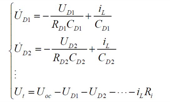 | (1) |
The commonly used equivalent circuit models of power battery including Rint model, Thevenin model and dual polarization (DP) model, are special cases of n-RC model when n = 0, n = 1 and n = 2. Their state space equations is shown in Table 1. These three commonly used models are explained as follows.
Table 1 The state space equations of three commonly used equivalent circuit models
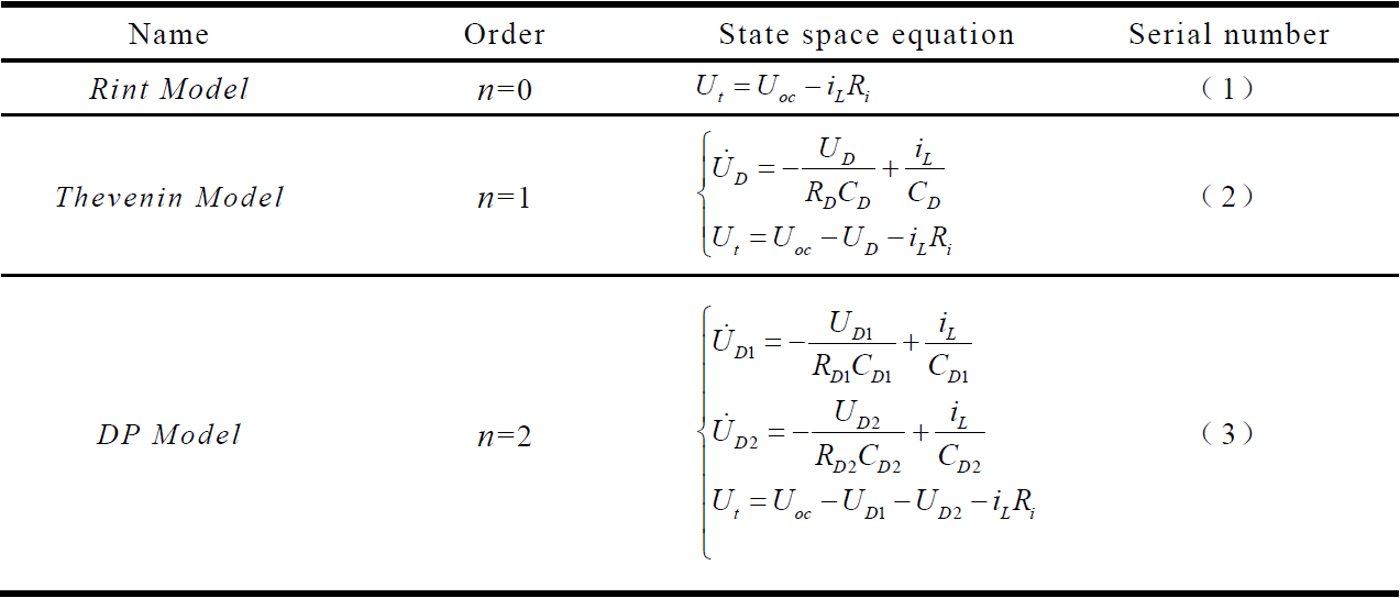
(1) The Rint model uses the ideal voltage source UOC to describe the open circuit voltage of the power battery, and the ideal resistance Ri to describe the ohmic internal resistance of the power battery. UOC and Ri are functions of SOC and temperature. Rint model is the simplest equivalent circuit model, without RC network. Its state space equation is shown in the formula (1) in Table 1.
(2) Compared with the Rint model, the Thevenin model uses a set of RC networks to the polarization characteristics of the power battery. The state space equation of the circuit model is shown in the formula (2) in Table 1, where RD and CD are polarization internal resistance and polarization capacitance, and UD is the voltage drop of the RC parallel link, which is used to simulate the polarization voltage of the power battery.
(3) The DP model adds a set of RC networks to the Thevenin model to describe the polarization characteristics of the power battery. The state space equation of this circuit model is shown in the formula (3) in Table 1.
2. Mathematical Equations
In order to facilitate the application in BMS, the model needs to be discretized. The following takes the n-RC model as an example to derive the discrete form of the model.
The transfer function of the n-RC model is:
 | (2) |
Let EL(s)=Ut(s)-UOC(s), then
 | (3) |
The bilinear transformation method shown in formula (4) is used to map formula (3) based on the s-plane to the z-plane.
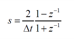 | (4) |
In the formula, Δt is the sampling interval time of the system. The equation based on the z-plane is
 | (5) |
In the formula, ci (i=1,2,...,2n+1) are the coefficients related to the model parameters. Equation (5) can be transformed into the discrete time domain, and the result is
 | (6) |
Since the open circuit voltage of the power battery is coupled with the SOC, working temperature T and the aging state Age ,the open circuit voltage UOC ,k at time k is defined as a function of the SOC value zk ,the temperature value Tk and the aging state Age ,k namely
 | (7) |
Then the derivative of UOC ,k with respect to time can be expressed as
 | (8) |
Considering that the actual sampling frequency of BMS is relatively fast, and the sampling time interval is generally less than 1s, three assumptions can be made as follows:
Assumption 1: The impact of the power consumed or absorbed by the power battery in the unit sampling interval Δt on the SOC is approximately zero, that is, dz/dt≈0.
Assumption 2: The temperature of the power battery does not change within the unit sampling interval, that is, dT/dt≈0.
Assumption 3: The aging state of the power battery in the unit sampling interval is unchanged, that is, dAge/dt≈0.
Based on the assumptions above, formula (8) is equal to zero. Then in the discrete time domain,
 | (9) |
So, formula (6) can be simplified as
 | (10) |
Define the data matrix and parameter matrix of the system as
 | (11) |
Then, formula (10) can be simplified as
 | (12) |
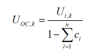
Based on the identification result of the parameter matrix, the identification of the model parameters can be realized. For example, OCV can be parsed as
 | (13) |
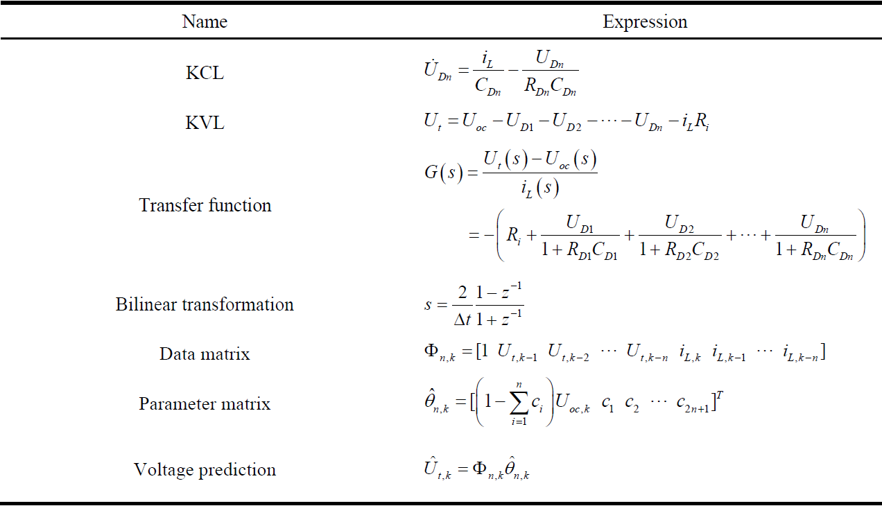
In summary, the n-RC model can be summarized as shown in Table 2.
Table 2 N-order RC equivalent circuit model formula
3. Main Results
The comparison curve of the voltage error of the equivalent circuit model is shown in Fig. 2.
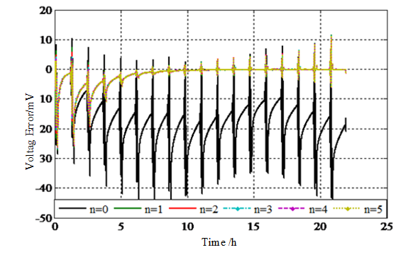
Fig.2. Voltage estimation error
Fig. 2 depicts the relationship of voltage error with time, indicating that except for the Rint model, equivalent circuit models combined with online data-driven parameter identification methods can achieve reliable identification, with the maximum error within 30mV.
4. References
[1] R. Xiong. Core Algorithms of Battery Management System. Beijing:China Machine Press,2018. (Chinese) (Chapter Three Section Two)
[2] H. He, R. Xiong and H. Guo, “Online estimation of model parameters and state-of-charge of LiFePO4 batteries in electric vehicles”, Appl Energy, vol. 89, no. 1, pp. 413-420, Jan. 2012. (Download)
[3] H. He, R. Xiong, H. Guo and S. Li, “Comparison study on the battery models used for the energy management of batteries in electric vehicles”, Energ convers manage, vol. 64, pp. 113-121, 2012. 96. (Download)
[4] H. He, X. Zhang, R. Xiong, Y. Xu, “Online model-based estimation of state-of-charge and open-circuit voltage of lithium-ion batteries in electric vehicles”, Energy, vol. 39, pp. 310-318, 2012. (Download)
[5] R. Xiong, H. He, F. Zhu, “Identification of dynamic model parameters for ultracapacitor used in electric vehicles”, Journal of Beijing institute of technology, vol. 20, no. suppl.2, pp.204-210, 2011. (Download)
[6] C. Lin, H. Mu, R. Xiong, “Multi-model probabilities based state fusion estimation method of Lithium-ion battery for electric vehicles: state-of-energy”, Appl Energy, 2017, vol. 194, pp. 560-568, May 2017. (Download)
5. Available resources
(1) Equivalent circuit model data: Click to download(monograph chapter)


