Charge
1. Optimized charging of power battery
Charging is the energy supply method of the power battery, and it is the main component of the power battery's full life cycle. In recent years, 31% of spontaneous ignition accidents of new energy vehicles represented by electric vehicles have occurred in the charging stage. The development of power battery charging methods is no longer only focusing on accelerating charging speed and improving user experience, but also ensuring that the safety, reliability and longevity of the product. Therefore, shortening the charging time, improving the charging efficiency, and ensuring the safety, reliability and longevity of the power battery during the charging process are the research focuses and difficulties in the development of new energy vehicles in recent years. Early power battery charging was mainly constant current charging and constant voltage charging. Through continuous development and improvement, constant current and constant voltage charging, multi-stage constant current charging, current and voltage pulse charging, continuous alternating current and AC charging methods, model-based series of optimized charging, fast charging were derived.
Constant current and constant voltage charging
Constant current and constant voltage charging(CC-CV) uses constant current to charge firstly, until the power battery voltage reaches the preset value, and then switches to constant voltage charging. Finally, the termination condition is that the charging current reaches the cut-off current value. The charging process is shown in Fig 1. Constant current and constant voltage charging method has less damage to the power battery, does not need to obtain an accurate circuit model in advance, has strong versatility, and is easy to realize the hardware circuit, so it is widely used, and is the most common charging method in the application of lithium ion power battery. However, the stage of the constant voltage charging takes a long time and is not suitable for rapid charging and discharging occasions.
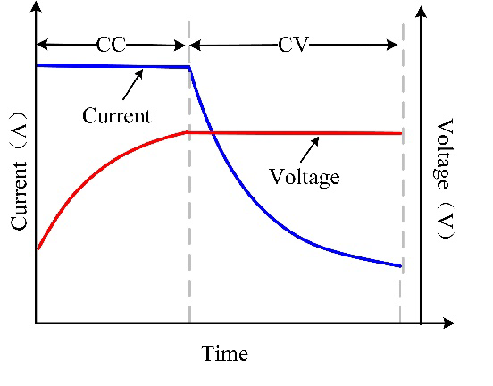
Figure 1 Constant current and constant voltage charging curve
Multi-stage constant current charging
The multi-stage constant current charging method consists of several constant current charging stages, as shown in Fig 2. When the power battery reaches the upper cut-off voltage or SOC in the first constant current charging stage, it jumps to the next stage and so on. In order to prevent the power battery from reaching the upper cut-off voltage too quickly, the design current of each constant current charging stage decreases step by step, and the charging is terminated by traversing all the preset constant current charging stages of the power battery condition. According to the different jump conditions between stages, the multi-stage constant current charging method can be divided into the charging method with the above cut-off voltage as the jump condition and the charging method with the SOC interval as the jump condition.
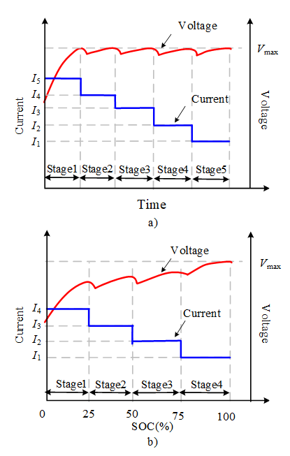
Figure 2 Multi-stage constant current charging curves
a) The above cut-off voltage as the jump condition b) The SOC interval as the jump condition
Pulse charging
The pulse charging method can reduce the polarization voltage through short-term discharge or rest, so that the next waveform cycle can obtain a higher charge current acceptability than other charging methods, increase the charge and discharge power, and reduce the charging time of the power battery. Pulse charging can be achieved by applying pulse current or pulse voltage.
Fig 3 shows the basic idea of the pulse charging method. Pulse charging generally consists of several sub-processes with Tc as the time period. Each sub-process is divided into two stages: in the first stage, the power battery uses Ic as the pulse current to charge for a duration of Td; in the second stage, the power battery uses Id as the current to discharge for a duration of Tc-Td, and Id can be 0. As the experiment progresses, the terminal voltage of the power battery continues to rise, and reaches a predetermined cut-off voltage as the termination condition.
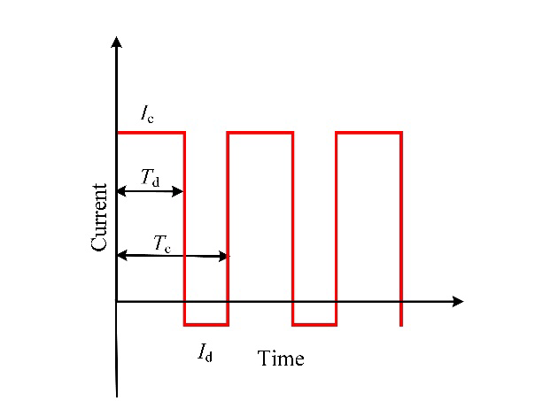
Figure 3 Pulse charging charging curve
AC charging method
The AC charging method is a kind of power battery charging method that uses continuous periodic alternating current as the charging excitation source. Sinusoidal Ripple Current (SRC), which is charged by sine wave Current, is one of the most representative AC charging methods. Different from the pulse charging method, SRC uses the superposition of sinusoidal current and direct current as the charging current, and the amplitude of the charging current always changes with time. SRC needs a power battery model when looking for the optimal charging curve, but unlike the model-based charging method, it adds an AC component to the charging current. As shown in Fig 4, the second-order RC power battery model is composed of a resistor Ra and two RC parallel circuits in series. The impedance of power battery containing DC component can be obtained by fitting voltage and current waveforms at different frequencies during SRC charging process, so as to be applied to simulate SRC charging process. The core of SRC lies in the calculation of the optimal charging current frequency, which usually uses the analysis of electrochemical impedance spectroscopy (EIS) to find the frequency corresponding to the minimum impedance.
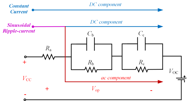
Figure 4 Second-order RC power battery model
Model-based optimized charging method
The model-based charging method is a kind of charging method that uses the description ability of the power battery model to optimize the charging performance. Its core is to master the characteristics of the power battery through modeling, and based on this, formulate a charging strategy for the expected optimization goal. Different from the waveform-based charging method, the model-based charging method provides deeper and wider control over the internal and external characteristics of the power battery, and is a charging method with good application prospects. According to different models, model-based charging methods usually include equivalent circuit model-based and electrochemical model-based.
The method based on the equivalent circuit model first needs to establish the equivalent circuit model of the power battery. Temperature is usually a feature that is widely concerned during the charging process of the power battery. Therefore, the temperature change of the power battery during the charging process can be considered by establishing a temperature model. It is worth noting that the coupling of the equivalent circuit model of the power battery and the temperature model is often used in a multi-stage constant heat rate charging strategy. The fundamental problem to be solved in the optimization of power battery charging is to minimize the power loss of the power battery to absorb energy. Because the electrical structure of the equivalent circuit model is simple and clear, it is often used in conjunction with the power battery power loss model to minimize the charging power loss.
Due to the simple structure of the equivalent circuit model, it is impossible to consider the internal chemical reaction process of the power battery such as the internal potential, the change of lithium-ion concentration, and electrochemistry of the power battery. In order to further adapt to the internal mechanism of the power battery, an optimized charging method based on an electrochemical model can usually be used.
Fast charging method
The fast charging method of power battery refers to a kind of charging strategy that takes measures to eliminate or reduce the polarization of the power battery to maximize the current acceptance ability of the power battery without affecting the age and safety of the power battery. Different from the traditional charging method, the fast charging method usually has a clear performance target. The Ministry of Industry and Information Technology of China recommended in the "Automotive Industry Technology Progress and Technological Transformation Investment Direction 2010" that the goal of fast charging is to charge the power battery from 0% to 80% within 0.5h.
The fast charging method of power battery can follow the charging method system of traditional power battery, but the high rate and high performance requirements of fast charging have brought some new challenges. For example, the optimization variables, optimization boundaries and constraints in the traditional optimized charging are no longer suitable for fast charging. The models in the traditional charging methods mainly focus on small charging rates below 1C, while the models in the fast charging method need to have more than 1C. With the maturity of fast charging conditions, the charging method system of traditional power batteries has begun to continuously improve and develop in response to the application requirements of fast charging, and more forms of fast charging strategies are constantly being proposed.
2. Optimization process
In order to determine the order of the multi-stage constant heat production rate charging strategy and the heat production rate value of each stage, it is necessary to establish the function of charging time, temperature rise, and charging power

In the formula, β is the target weight coefficient of charging time and temperature rise. t is the charging time, Tc is the temperature rise, a and b are the normalized processing coefficients of the equation.
In the optimization process, in order to ensure the safety of the power battery, the following constraints need to be introduced
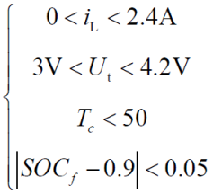
In the formula, SOCf is the final charge into electricity.
The above optimization problem can be solved by genetic algorithm, and the implementation process is shown in Fig 5.
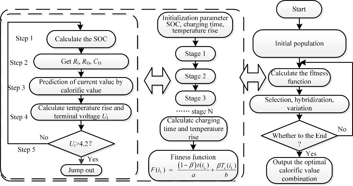
Figure 5 Optimization process of genetic algorithm
3. Simulation results
Set SOCf as 0.9 and Tmax as 50℃ to analyze the power battery. Taking β as 0.24 and the third order as an example, the third order constant heat production value was optimized by genetic algorithm to be 0.36W, 0.27W and 0.19W. The charging curve of the power battery is obtained, as shown in Fig 6. The charging time of the power battery is 3563s and the temperature rise is 1.07℃.
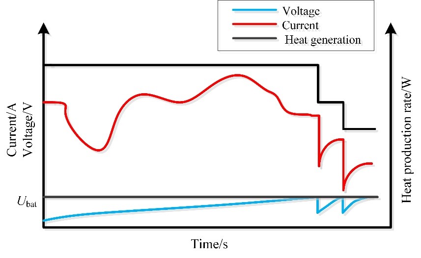
Figure 6 Third order constant heat production value and charging current
4. Experimental verification
In order to evaluate the advantages of this charging method compared with the traditional CCCV method, a comparative experiment was carried out on the power battery at 25℃. The result is shown in Fig 7.
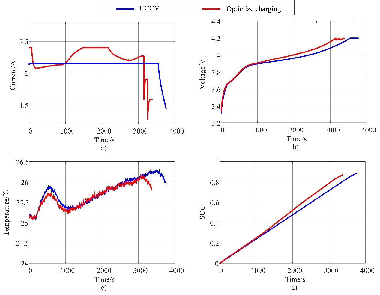
Figure 7 Comparison of optimized charging method and CCCV
a) Current curves b) Voltage curves c) Temperature rise (d) SOC
Table 1 Comparison of optimized charging method and CCCV

The results show that, compared with the traditional CCCV charging method, the multi-stage constant heat production rate charging method based on the model can shorten the charging time by 7.89% and reduce the temperature rise by 38.8%, which is a feasible optimal charging method.
5. References
[1] R. Xiong. Core Algorithms of Battery Management System. Beijing:China Machine Press,2018. (Chinese) (Chapter Nine)
[2] R. Xiong, W. Sun, Q. Yu* and F. Sun, “Research progress, challenges and prospects of fault diagnosis on battery system of electric vehicles”, Applied Energy, vol. 279, pp.115855, Dec 2020. (Download)
[3] R. Xiong*, Y. Pan, W.X. Shen, H. Li and F. C. Sun, “Lithium-ion battery aging mechanisms and diagnosis method for automotive applications: Recent advances and perspectives”, Renewable and Sustainable Energy Reviews, vol. 131, pp. 110048, Oct 2020. (Download)
[4] R. Xiong*, S. Ma, H. Li, F. Sun and J.Li, “Towards a Safer Battery Management System: A Critical Review on Diagnosis and Prognosis of Battery Short Circuit”, iScience, vol. 23, no. 4, pp. 101010, Apr 2020. (Download)
[5] M. Ye, H. Gong, R. Xiong* and H. Mu, “Research on the Battery Charging Strategy With Charging and Temperature Rising Control Awareness”, IEEE ACCESS, vol. 6, pp. 64193 – 64201, Oct 2018.(Download)
6. Available Resources
(1) Optimize charging information: click to download(![]() Optimize charging)
Optimize charging)


